
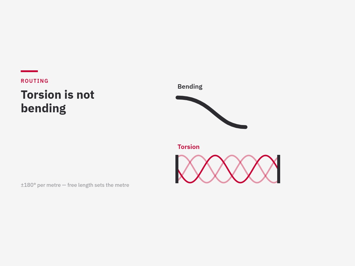
Most cable-management mistakes are made before anything is built, in the decision about where the package runs. These are the rules we apply, and the reasoning behind them, so you can apply them to your own cells whether or not we build the pack.
Torsion versus bending: the distinction that matters most
Bending and torsion are different loads and cables are rated separately for each. Bending flexes the conductor over a radius. Torsion twists it about its own axis, working every strand against its neighbours along the full length between two fixed points.
Robot arms do both, but the wrist axes are dominated by torsion, and torsion is what usually ends a cable’s life. The practical consequences:
- Use cables with an explicit torsion rating on axes 4, 5 and 6 — a bend rating alone tells you nothing about how they will behave there
- Specify the torsion per metre, not in total. A ±180°/m cable in a half-metre free length is being asked for ±360°/m
- Give torsion somewhere to distribute. A twisting cable clamped at both ends of a short run has nowhere to spread the load, and fails at the clamp
- Never let a cable take torsion and its tightest bend at the same point in the cycle
Bend radius
- Respect the dynamic minimum bend radius, not the static one — they are different numbers and the dynamic one is larger
- Check the radius at full extension and at the extremes of wrist rotation, not at the taught home position
- 12× outer diameter is a common design target for high-flex data cable; tighter constructions exist — some feedback cables go down to 2×D — but that is a specification to confirm rather than assume
- When in doubt, give more radius. There is no failure mode caused by a radius that is too generous
Fixing points
- Fix the package at defined points on each axis, not only at the base and the tool
- Every fixed point divides the free length — which changes the torsion per metre either side of it. Moving a clamp is a design change, not an adjustment
- Clamp each core at its own diameter. One ring around a whole bundle lets the cores migrate and breaks them at the clamp
- Leave service loops where a technician will need slack to work — and make sure those loops cannot foul anything through the cycle
Separation
- Keep power, weld current and signal apart. Weld current in particular induces noise in anything running alongside it
- Run process media — air, coolant, adhesive, rivet feed — so that a leak drains away from electrical cores rather than into them
- Keep anything consumable or frequently replaced accessible from outside the pack
Prove it before you build it
Reach, cycle time and cable path should all be demonstrated in simulation before the first bracket is cut. The first time the robot moves should not be the first time anyone has checked that the package fits — and the routing is the part most often left until it is too late to change cheaply.
Related reading
What is a dress pack · Why robot cables fail · Maintenance checklist · Custom dress pack design
Send us a cell layout and we will tell you what we would change.